


Buildings in 2D
How does one model a building in a 2D floodplain?

Boy, have methods changed. If we have a building in a flood model, we would block out the footprint with an ineffective area of the footprint at the cross-sections where the physical building would appear.
I recall a client who wanted to build on a parcel that fell in a floodway in Illinois. The parcel was effectively limited by the footprint of the prior building and in the shadow of two bridges. We did elevate the building, but the impact of the new building would NOT change or impact a 1D flood model due to the overlapping ineffective flow areas in the model. I am having trouble remembering if we modeled it at all or mapped the cross-sections and inactive flow area shadows of the buildings and bridges to find the location we found.

1D models had difficulty with buildings because they “jumped” space between where the engineer judged where to place the cross-section. The effort might have been too much to consider in the DOS days or punchcard days.
2D Models
How might you model a building in a 2D domain? There are a few ways.
WAYS OF OLD
One of the first 2D models I reviewed came from HEC-RAS, and the buildings were burnt into the terrain. One shouldn’t call that a terrain but rather a digital surface model. (DSM) This surface was used in the early HEC-RAS 2D model for flood routing. The flood model routed water around buildings and eventually into and out of the ball field below.

Water cannot penetrate a building as roofs and footprints were treated as the ground model in the 2D model.
In the XPSWMM training class on 1D/2D modeling, buildings were discussed in four main categories. I’ve annotated a photo from the training manual, which is as follows.

Inactive Polygon: Cell size-dependent issues - likely will miss key features but act as glass water for the inactive cell. Water doesn’t go in, and rain won’t occur on an inactive cell. The training does indicate that this “might not always be good modeling approach.”
Fill Polygon at Finish Floor: In this case, if the finish floor is known, the elevation of the building is added to the mesh. The home will flood (volume available)
XPSWMM Landuse Polygon: This establishes the high Manning n value. Interestingly, the training suggests the following values: 2, 0.3, and 3. The Harris County Flood Control District 2D modeling suggests using 10! Multiple roughness values are possible based on depth with XP and TUFLOW.
Flow Constriction Layers: The layered flow constriction option might allow for the definition of the ability of water to enter the building due to blockage based on levels. While generally used for bridges, this could be used for elevated structures that allow free flow to a specific elevation and then offer resistance to a second level before fully overtopping at the last elevation.
XPSWMM allows multiple elements to come into play due to TUFLOW's capabilities in the 2D domain. Similar recommendations exist on TUFLOW’s wiki here.
InfoWorks ICMs recommended modeling buildings as holes in the 2D mesh for years. “Voids are the regions within the 2D zone that will not be meshed, e.g., buildings.” (InfoWorks Help) While this is similar to XPSWMM Inactive Polygon - the irregular mesh of InfoWorks ICM would, or could follow that building footprint.
InfoWorks ICM has porous walls and porous polygons that allow a fraction of the water to pass, but it also includes a failure mechanism, aka collapse, which one could do in XPSWMM and TUFLOW.
How do these play in the 2D domain?
EFFECTS
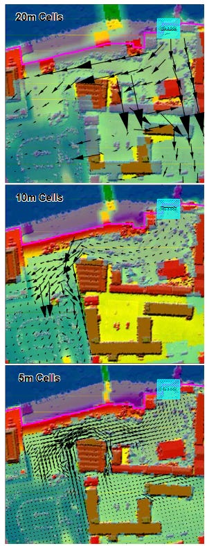
TUFLOW’s Bill Syme presented a paper in 2008 that discussed the effect of these methods for modeling buildings. (TUFLOW PAPER 2008) The paper initially discussed cell size impact. As you can see in the screenshot below, the inactive areas around the buildings, at the larger cell size, are ill-fit until a small enough cell size is found.
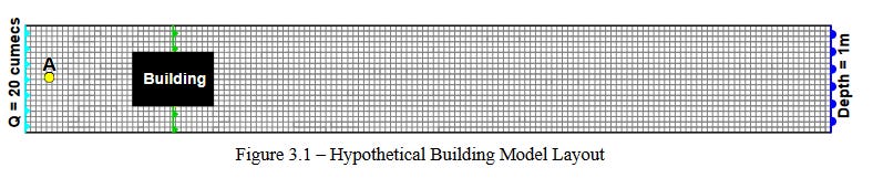
The paper then discusses and demonstrates a hypothetical model's various building modeling types. The domain is a simple 2D grid and a building in the middle.
The results are graphed along the centerline.
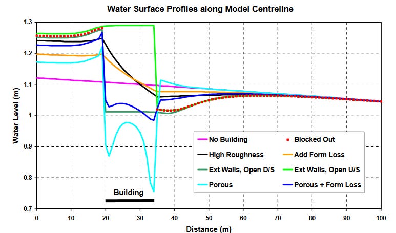
I find the test and paragraphs that follow the discussion of the results interesting. (Emphasis is mine)
As previously discussed, the use of a higher Manning’s n value is a common method for representing the energy dissipation caused by buildings. The difficulty faced by the modeller is how much higher should the Manning’s n value be?
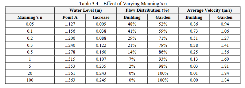
The Higher Roughness scenario was simulated using a range of Manning’s n values to ascertain their influence. Table 3.4 presents the results from these simulations. As indicated by the results, the effect of the building on upstream flood levels and flow distribution between building and garden varies significantly depending on the Manning’s n value. A Manning’s n value of about 0.4 would provide a similar increase in water level to that provided by the Blocked Out scenario, which represents a 50% blockage. More expansive testing could provide indicative Manning’s n values for a range of blockage scenarios.
The resulting variation of Manning’s n tests showed that much higher n values might overestimate flood heights around buildings, and increase velocities around the buildings.
The new Wu Viscosity formulation came after this paper, so using a Manning n value of 10 is inappropriate. The TUFLOW log file will reference warning 2583, which includes the following:
The Wu eddy viscosity formulation is based on bed friction velocity, which in turn is dependent on manning's number. High manning's numbers produce very high viscosity values, which in turn can limit the model timestep through the diffusion or Peclet number (reported as “Nd” in the HPC output). In general, in areas where very high manning's numbers are used (for example the slowing effect of buildings may be represented as increased surface roughness), the flow velocity is much slower and the elevated viscosity has little effect, other than to slow the simulation down. An upper limit to the manning's number used in the Wu viscosity calculation was introduced in the 2023-03-AA release to limit the computed viscosity in regions of unusually high roughness. A manning's value of 0.1 was selected based on tests that indicated this value provides a sensible compromise whereby the majority of models would not be diffusion number controlled while keeping changes in results to a minimum.
In the next post, I will discuss some of the newer ways, including what to do about rainfall. How will that come into play?
Maybe I should build a new test model with the quadtree mesh…