Let’s cover several Autodesk tools for culverts. I have always felt that the culvert was Autodesk Civil Infrastructure tool’s most significant weakness. As a customer from DCA/Softdesk/LDD/C3D, we always used a LISP program that allowed the drafting of two parallel lines and a half-circle end section to illustrate the 2D CAD version of a culvert. We considered alternatives, such as a single line for the culvert barrel and triangles for the two end sections—regardless of the end treatment of the culvert.
This is the simplest ‘CAD’ drawing of a culvert. Very little information short of diameter, length, and inverts of the pipes were the only information labeled.
When we migrated to Civil 3D, pipe networks with Civil 3D’s inlet-outlet structures were weak. We didn’t do many culverts, as most projects were sewer networks. Building part-builder structures for end sections is challenging. Civil 3D Structures are not multiple barrels without resorting to some fun. Those were some of the reasons that InfraWorks got culverts.
InfraWorks
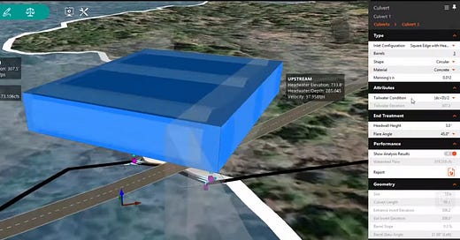
The product introduces watershed analysis and places culverts where the streams cross the design road. We could use USGS Regression Equations to size a culvert for that flow and the allowable HW/D. It was multiple barrel capable with circular and box culvert shapes. Infrastructure Part Modeler built these parts.
The fun element was designing the visualization of the analytics and the report. The view projected the culvert above ground and drew the water surface profile in that projected view - providing a quick answer to ‘will it work’?
Disappointingly - the 3D culvert never makes it to Civil 3D.
ESRI will get the design if it is published.
Hydraflow Express
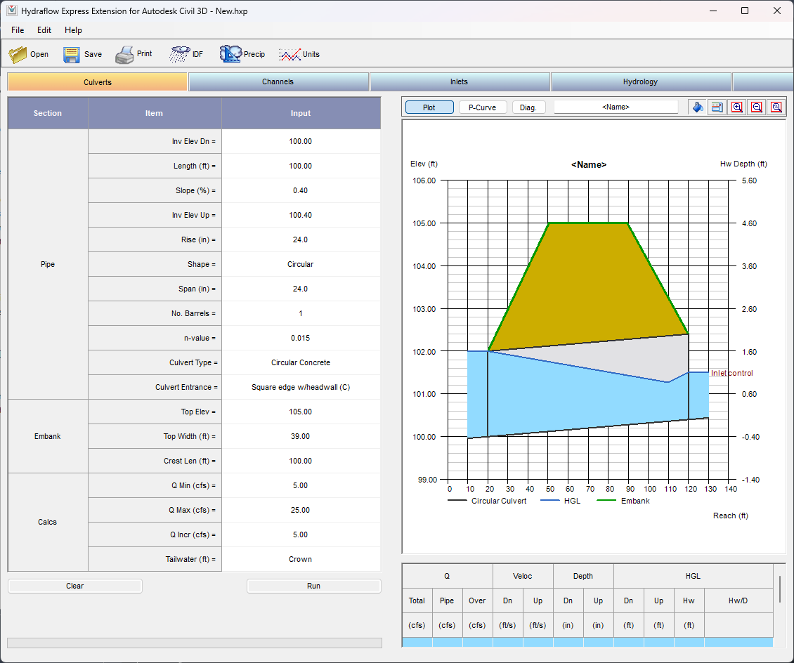
It’s a simple calculator. As one trainee stated in a class I taught, "Why would I use this? It’s too simple—I prefer HY-8.” It’s hard to quibble with that assessment. Oversimplifying the analysis does not gain anything, as the value provided in HY-8 greatly exceeds Express. Well, at least Express’s report is a single page.
Yikes! User beware! That doesn’t look correct to me.
At least Shape controls Culvert type, and the standard 57 types are available.
Sanitary and Storm Analysis (SSA)
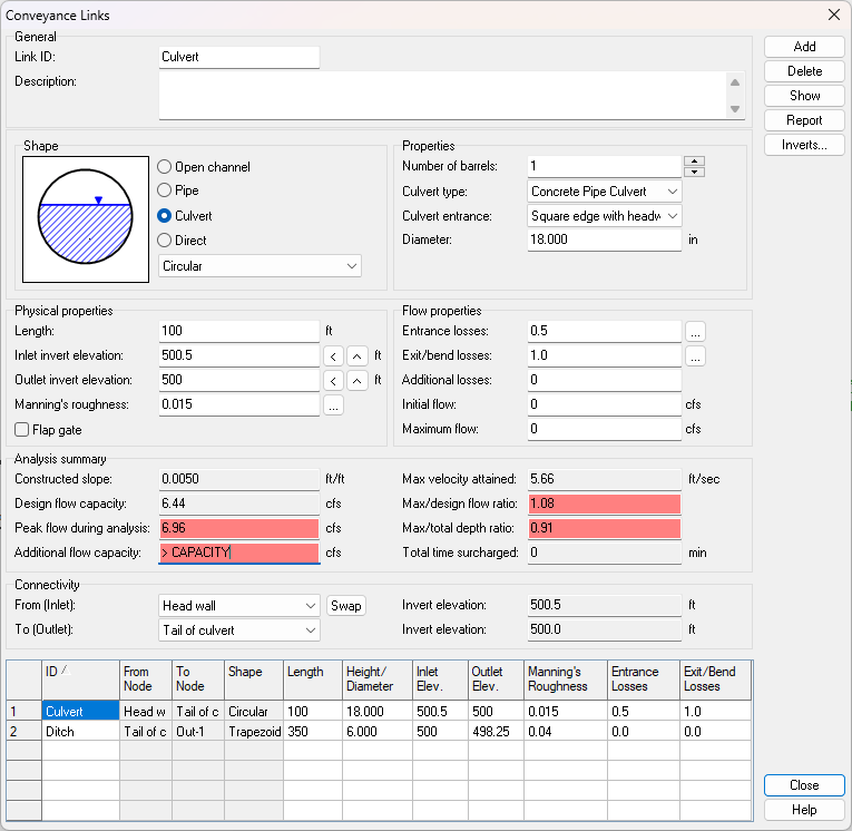
As this is based on EPA-SWMM, the standard 57 culvert types from the older HDS-5 are applied to the pipe barrel and not the upstream or downstream nodes. This is because SWMM elements are functionally a node-link data structure event, making a clean transfer between Civil 3D and SSA an uneven set of assumptions. For example, if the upstream Civil 3D structure is an inlet-outlet, SSA will assume a culvert for modeling purposes.
Most modelers forget to put storage on the upstream headwall, and the design meeting an allowable HW/D ratio is challenging to find explicitly, such as the HW in the node result and the diameter in the pipe.
XPSWMM
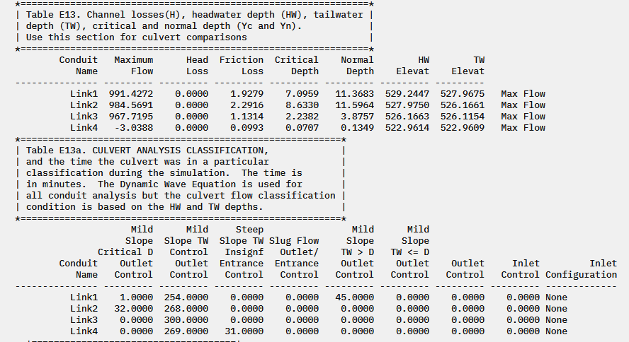
XPSWMM is built on the SWMM4 engine, so it’s similar to EPA-SWMM and other simulation software. However, the reporting is different. It’s helpful.
This emphasizes the culvert's importance as an element that isn’t simply static—it can vary across a simulation, or it could.
Saving the 2D Culverts for a TUFLOW discussion cause, well, XP2D is TUFLOW.
InfoWorks ICM
With the addition of the SWMM Network, the InfoWorks network gained the similar culvert functionality of simply selecting the “The selected code determines the values that the software automatically assigns to the K, M, c, Y, and Inlet headloss coefficient (Ki) fields if the #D flag is set on those fields. The assigned values are defined in the Hydraulic Design of Highway Culverts, Third Edition” (Autodesk Help)
If you want to use the South Dakota Box entrance types for multiple barrel pipes - you can manually enter the K, M, c, and Y values. Oh, boy.
I still am scratching my head with wide culverts and 2D point connections. The 2025 2D Line helps make that point, but gaining stability is a tough nut to crack, except in ideal situations. “This is because the 2D culvert flow calculations are based on empirical equations, not shallow water equations (as used by 2D conduits), so flow reversals may occur at the calculated 2D-time step.” (Autodesk Help)
This simulation software operates across the entire network’s context into the model run. Iterate on a size - review the results. I hope you didn’t mesh between scenarios on a design; otherwise, you are back to the kaleidoscope found here:
Until next time…



It never seemed to make sense that anyone would think to create multiple products from scratch and not make them talk to each other. This shortsighted thinking leads to horrible workflows like IMX export/import.